Share
Pin
Tweet
Send
Share
Send
Although there are many varieties of instant coffee on the shelves, real connoisseurs of this drink, such a product is not entirely satisfied. So, as the main invigorating substance - caffeine, it practically does not remain in it, after processing and drawing.
Therefore, in order to get a drink with better components, you must have a coffee machine, which is not entirely available, or grind fried grains in a coffee grinder and then prepare them in a Turk on a stove.
This option is not new and does not require large cash costs. Many remained Soviet coffee grinders, and imported, more practical devices for everyday use appeared in household appliances stores.
In modern coffee grinders, almost nothing has changed, compared with their domestic counterparts. The principle of operation remained the same, the only thing added was electronic control.
If we talk about the quality of products, then it does not particularly shine, so the device periodically needs repairs of varying complexity.
Here, in the photo, the coffee grinder with a problem in operation, that is, it does not react either to the inclusion in the network, or to pressing the control buttons.
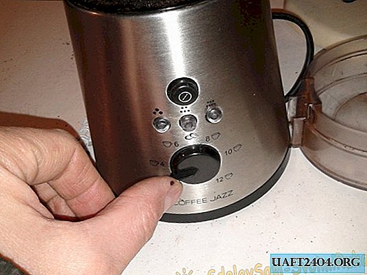
There were no short circuits, cod and smoke from it. She just stopped working.
We proceed to disassemble.
We put the device on its side and grabbing the regulator’s engine with our fingers, remove it.

Next, using a thin screwdriver, remove the bottom from the latches.
It rests on four latches and grooves in the housing.

In this coffee grinder there is a coil with a handle for rotation with which, for convenience, the wire "hides" inside the case. In this regard, the power cable has rotating contacts on the bottom.

These contacts in the form of a block are removed with the cable.

Then, unscrew the four screws securing the extra sole.
Having removed it, you can see the engine itself, the electronic circuit and other details necessary for diagnosis.

I immediately want to note the extreme inconvenience of inspection and diagnostics in general, since the wires are very short and thin, and everything is compact and compact.

Mostly, wires going to the board and one wire from the engine interfere.

To continue working, it is necessary to disconnect the wires from the board and this can be done without a soldering iron, since the connection is made on the connectors.
But to remove these connections with your fingers is not so simple, a screwdriver with a direct tip will help here.


In this way we do with the rest of the compounds.

It would be nice to sketch or take a picture before removing the color of the wires, where which one is located so as not to be mixed up during the next connection.
When the wires are removed, the electronic board can be pulled out of the housing and free access to the engine.


The motor cannot be pulled out until a knife is fixed on its axis. It is wound counterclockwise, since the thread here is left. Therefore, unscrew the knife clockwise, and to fix the axis of the engine, insert a screwdriver into a special slot, as shown in the photo.


As soon as the knife is removed, the engine will easily come out of the housing.


Now we remove additional parts from the rotor, remembering the sequence of their installation.


Try to rotate the motor rotor with your fingers. If the rotation is tight, then it is necessary to disassemble the engine, wipe and lubricate the rubbing parts.

In our case, the rotor rotates freely, but additional lubrication will not hurt. This can be done without disassembling the motor.

We take grease on the tip of the screwdriver, and apply it to the axis, next to the bearing. Next, we move the rotor axis from top to bottom. Thus, part of the lubricant will get inside the sleeve. This will give a better glide, which does not hurt at all, especially since there is an opportunity to do it.
After that, check the length of the collector brushes. If they are short and practically fall out of the inserts, then they should be replaced.
Next, we go on to check the integrity of the cord and the power connector.
Coffee grinder repair
To do this, disconnect it from the sole and turn on the plug in the network. Using a voltage indicator or an AC voltmeter, measure the voltage at the contacts. How to do this can be seen in the photo.


The pointer shows 220 volts, so the cord and connector are in order.
Now, we check the operation of the accidental protection switch. During operation of the coffee grinder, its closed lid presses on the glass rod, which in turn presses on the switch and closes its contacts.
Therefore, we connect the ends of the device with the terminals of the switch and press its button.

During normal operation, the device will show a short circuit. If it does not exist, then the matter is in it, that is, replacement cannot be avoided.
Now we pass to check of the engine. We insert the board into special grooves, and put the engine next to it on its side.

Also, insert the power connector with the cord into its place (in the bottom of the case) and turn on the power plug.
It is also necessary that the switch contacts are closed at the time of verification, this can be done by inserting a plastic rod, in the same way as in the photo.

You can of course hold the button with your finger at the time of start-up, but this is not entirely safe in the event of a short circuit in the motor winding.
To now check whether voltage is coming to the motor and the board, we connect one end of the pointer to a common wire, and the other to the switch terminal.

The pointer should show the presence of voltage, as in the photo.
If there is no voltage, then the problem should be sought in the sole supply connector.
Disconnect the power plug from the mains.
When we checked the presence of voltage, and it is, we connect the connectors with the corresponding contacts on the board.

The one that comes from the engine and to the board (common) is connected with a piece of copper wire, from the connector to the corresponding pin. This must be done so that the engine can be checked while lying down, as it is more convenient and safer.

When the circuit is assembled, turn on the power plug in the network, and gently holding the engine, press the button for selecting the degree of grinding (one of three).
One of the LEDs on the control board should light up. Next, press the start button.
The engine does not rotate, but when one of the connectors on the board moves, rotation periodically appears and disappears.
It was exactly the connector where we connected the engine to the board, using a wire.
Subsequent verification of the circuit of this section showed that in the place of soldering the plug, microcracks formed on the board and there was no good contact, respectively. The device did not show the circuit, from the plug to the place of its soldering on the board.

The problem was solved by soldering this place, it is also desirable to solder the other two plugs using flux and tin.

Very good results are given by a flux made of 30% ground rosin and 70% alcohol. He well cleans the soldering place, and with it the connection is quite reliable.


When assembling, disconnect all wires from the engine, find and install the rubber gasket in its place. It should be installed exactly in the specified place.


Next, we put washers and a brass bushing on the engine axis.


Now, we are trying to insert the engine into the grinder body without breaking the wires, and so that its axis goes into the opening of the working bowl.


When this happened, holding the engine with your right hand, we wind the working knife counterclockwise.

Now the engine rests on its axis from above, and from below it should be fixed with a sole with a rubber gasket.
Before you put on the bottom, you must connect all three connectors on the board. To do this is inconvenient, but possible.
Also, we insert into the corresponding openings of the case, the "START / STOP" button and glass caps of the indicator of operating modes.
After that, aligning the engine casing approximately under the gasket seat - put on the pan.

The axis of the grinding time adjustment resistor should be approximately in the center of the hole in the apparatus body.

Next, we fix the lower part of the grinder body with a plastic sole.

We put on the regulator river, and turning on the coffee grinder in the network, we check the operation of the electronics. To do this, we put on the cover or press the rod of the protective switch with your finger, and try to choose the operating mode.


Different operating modes should be highlighted by the corresponding LEDs.
Having selected the mode, press the "START" button.

The coffee grinder must work for a certain time and turn itself off. Operating time depends on the degree of grinding. The larger it is, the less time it takes.
The repair is over and now you can again enjoy the taste of your favorite drink.
Share
Pin
Tweet
Send
Share
Send