Share
Pin
Tweet
Send
Share
Send
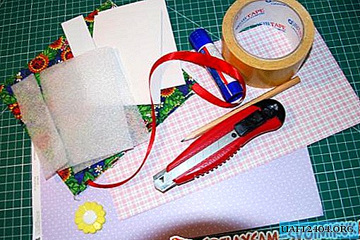
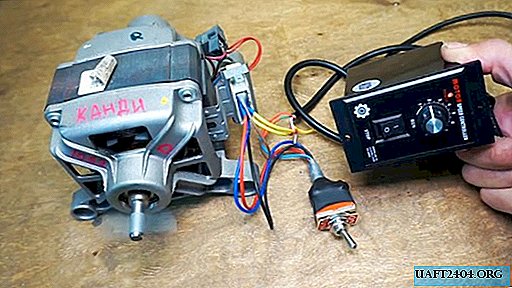
What is needed
- Toggle switch with two groups of contacts 220 V 15 A, you can purchase it on Ali Express.
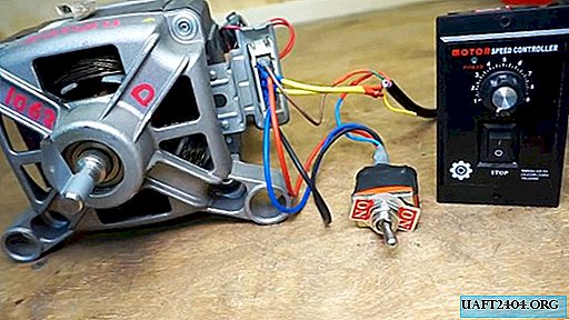
- Speed controller 400 W 220 V 50 Hz, also take on Ali Express.
- An electric motor from an automatic washing machine will suit almost any brand.
- Pigtails of various colors, preferably blue (zero) and brown (phase).
- An electrical tape is required, to install a powerful radiator, buy a new one and a tube of heat-conducting paste.
- To check the connection diagram, it is recommended to use an ordinary tester or at least an indicator.

Motor connection

Carefully inspect the terminals of the removed motor. It has six conclusions: two contacts go to the RPM sensor (tacho) and two contacts each from the rotor and stator windings.

We don’t need a tachometer, we don’t touch it, we only need to connect the engine.

All single-phase motors of this type are connected in the same way. The output of the stator winding must be connected to the input of the rotor winding. The remaining two ends are attached to zero and phase. It makes no difference which particular winding will be first and which second.

Identify the winding outputs on the connector. You need to use the tester, always keep one contact on the terminal, and apply the second one in turn to the others. If the device showed a short circuit, then two terminals are connected to one winding.
In our case, the bottom and second contacts are connected to one winding, and the second terminal is above the bottom and the third is above. Accordingly, we need to connect the second and third upper contacts with a jumper. Make a jumper and connect. For warranty, call again, now your short should show between the two remaining terminals.

Connect the voltage of 220 V to the two remaining ones, if everything is normal, the engine will begin to rotate.
Reverse connection
As mentioned above, to change the direction of rotation, it is necessary to interchange the connection of one of the windings to each other.

And the engine will begin to rotate in the other direction. Check that the connection is correct, swap the wires on the terminal strip according to the described circuit, turn on the voltage. The direction of rotation of the engine should be reversed.

The contact to which the phase was applied must be connected to the input of the second winding. The voltage falls on the freed terminal, the zero position does not change. Changing the connection order can be done by clicking the toggle switch.

Turn the toggle switch upside down, on the bottom there are signs for each output and a diagram of their connection in the left and right positions of the switch.
To facilitate understanding, draw an elementary connection diagram: two windings and two switch contacts. Middle contacts in turn connect / disconnect to the two side. Connection is elementary.

Connect one winding to the extreme lower contact and connect it with a jumper with the extreme upper contact. Connect the second winding to the middle terminal, so that in this example the stator winding will be connected in our example.

Now I began to connect the rotor. One contact of the toggle switch must be connected to the output of the rotor winding, and the second directly to the neutral power wire.
If everything is clear, then proceed with the connection. Make diagonal jumpers between the extreme terminals. One middle output of the toggle switch is connected to zero, and the second to the second winding.
Connect all the wires and check the correctness of the circuit again. Middle contacts: one to zero power, the other to the stator winding. The second end of this winding is connected immediately to the power phase (brown wire).
Contacts on the diagonals must have jumpers, wires from them go to the second winding (rotor). Before switching on, be sure to check the tester for changes in short circuit when switching the toggle switch.

Carefully insulate the contacts, check the functionality of the motor. When switching, the direction of rotation should change. It is strictly forbidden to change the direction of movement until the rotor stops completely.
Speed control, my revision
If you bought inexpensive Chinese products, you must definitely make an audit of the device. Remove the filling from the case and pay attention to the triac. In the best case, it has a very small radiator that cannot efficiently remove heat. In the worst case, there is nothing at all.

On a new radiator, cut the M3 thread, adjust its length to the size of the body. Spread the surface of the triac with thermal grease and fix the prepared radiator. Assemble the regulator.

Connect regulator
Inspect the device. On the back there is a bracket with connectors and a plug with terminals. Each contact is signed.


Find zero, phase, and ground at the entrance (if you have grounding in your home). Power is connected to them, in our case, zero and phase (there is no earth).
Now you should find the output of zero and phase from the regulator. The cover should be a detailed diagram indicating the purpose of each output wire and its color.
On the purchased regulator, yellow is the earth, two blue ones - to the tachometer sensor, red - phase. White and green are interchangeable, but for this you need to change the position of the jumper. In our case, green is involved. The connection is determined by nicking the terminals with a tester.
Connect the blue wires to the tachometer on the motor terminal block. In the example, zero (green) is connected to the middle terminal of the toggle switch, and phase (brown) to the free contact of the winding. The yellow wires on the terminal block are connected to the tachometer. Apply voltage to the speed controller and check the engine at all modes and speeds.

On the device case there is a special hole for adjusting rotation modes with a variable resistor. With its help, the step of changing the speed changes, the rotation of the rotor will begin not jerkily, but almost from scratch. Set the desired modes.
Conclusion
Any electrical work should be done in strict accordance with the EMP. If you cannot decipher these three letters without the help of the Internet, then you should not risk your health.
Share
Pin
Tweet
Send
Share
Send