Share
Pin
Tweet
Send
Share
Send
The main materials:
- electric motor with a pulley;
- a large pulley with an axle;
- drive belt;
- idler pulley or roller with axle and bearings;
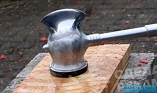
- sledgehammer;
- furniture wheel;
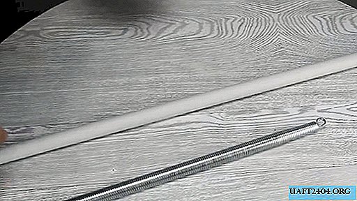
- anvil or spring;
- 2 tension springs;
- lanyard;
- slats and boards;
- aluminum strip 40 mm;
- plywood 20 mm;
- 2 case bearings on legs under the axis of a large pulley;
- square pipe 20x20 mm.
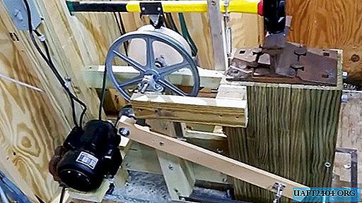
Making a mechanical sledgehammer
The base of the machine is a wooden workbench assembled from timber and planks. It consists of three supports for fixing the details of the mechanism. They are connected at the bottom by a common base and have an upper connection with a pair of bars.
An electric motor with a small pulley on the shaft is fixed on the side shelf of the first workbench support.

He is wearing a drive belt, stretched over a large pulley, fixed on a central support. It is mounted on a long axis, held by two housing bearings on the legs.

A large driven pulley is much larger relative to the leading one, which reduces the gear ratio from the electric motor, but provides power.

On the axis of the large pulley is fixed a home-made eccentric made of 2 fused plywood sheets. To protect against wear, it is covered with an aluminum strip.

The eccentric is fixed on the shaft tightly, so it rotates with a large pulley.

At the top of the first support, the end of the handle of the sledgehammer is fixed with a bearing, which allows it to move in the same plane. Next, a furniture wheel resting on an eccentric is mounted on the handle.

Above the beginning of the third support of the workbench, a rigid clamp is fixed to the handle of the sledgehammer with a spring pulling the hammer down.


A wooden frame is also provided to limit the upper stroke of the sledgehammer.
An anvil or rail is installed on the third support. Its height is selected so that the hammer, rested by the furniture wheel to the lowest point of the eccentric, reaches the anvil with a gap of a couple of millimeters.

A rail is attached to the upper part of the central support for one fixture so that its fixture is used as the axis of rotation of the entire shoulder. On the edge of the rail near the engine, a tension roller or pulley is fixed, whose task is to tighten the sagging drive belt. Using the lanyard, the second end of the shoulder is connected with a square metal profile almost parallel to it, located below. That also thanks to one fastener works like a shoulder. Its axis of rotation is also located on the central support, but lower. The free end of the square is pulled upward by a spring attached to the base of the anvil stand.
Using the lanyard, the distance between the rail and the square is adjusted in such a way as to obtain the tension of the drive belt on the motor when the foot is pressed against the floor of the square pipe.


To use the hammer, you need to start the engine. After that, pressing the foot on the steel square, you can pull the belt, after which the sledgehammer tossed by an eccentric and accelerated by a spring will begin to hit the anvil back. As soon as you release your leg, the belt will sag and the blows will stop.

Hammer in work:
Share
Pin
Tweet
Send
Share
Send