Share
Pin
Tweet
Send
Share
Send
Until recently, we heard about them as special means for the military, which use them for covert surveillance and combat operations in the dark. The capabilities of such devices are also used in modern conventional cameras. At the same time, some of them are able to distinguish objects in the infrared spectrum, while others are not. Today we will show how to make a night vision device from a conventional digital camera. So let's get started!

The principle of work and resources for homemade NVD
Our NVD is based on a digital camera, popularly known as a “soap box”. Electronic filling is saved, because through the LCD screen it is able to transmit images in real time. By changing the filtering of the lens and increasing the sensitivity of the camera to the infrared range, as well as equipping the camera body with infrared illumination, we open up new possibilities for a digital camera capable of capturing objects in the near infrared range. Also, such a device can be used as a thermal imager, distinguishing between heated objects, for example, an unattended iron, electric stove or kettle.
Materials:
- Digital camera;
- Infrared LEDs
- Cooling radiators for LEDs;
- Step-down voltage converter;
- Button - switch;
- AA battery 1.5 V - 2 pcs;
- Conducting, electrical tape.
Instruments:
- Soldering iron;
- Screwdriver with interchangeable nozzles;
- Paint knife;
- Hot glue gun;
- Tweezers.


We make the night vision device (NVD)
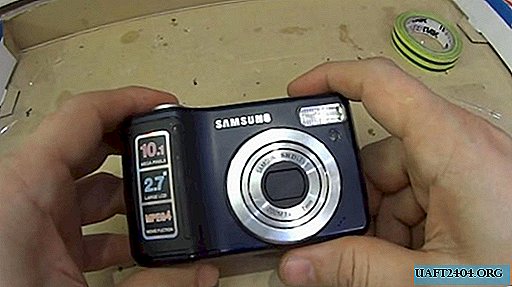
For this experiment, the author purchased a working Samsung S1030 digital camera. This is an ordinary soap dish with a sensitivity of 50 - 1600 ISO, a maximum resolution of 3648 x 2736, equipped with a 2.70 inch LCD screen on the rear panel.
Remove the infrared filter
Unscrew all visible screws from the back of the camera. This is easy to do with a screwdriver, making sure that nothing interferes with its dismantling. This must be done as carefully as possible, without damaging the plastic shutters and clips, as well as without pulling out the cables of the electronic filling.


We unlock the LCD screen, carefully removing it from the holder frame, which we also dismantle then. Loops from the LCD screen and camera control are released from the connectors. The information output control board should release the front cover, which can now be unfastened from the device.


The wiring leading to the microphone must be removed, or disconnect this element completely. Having gained access to the high-voltage capacitor for a flash, it is necessary to de-energize it with a resistor, voltmeter, tester or light bulb, shorting its contacts.


Having soldered off the power contacts, we remove the camera control board, leaving only the lens and the matrix. It is to her that we need to get close.


We unscrew the matrix board with a photosensitive sensor that captures the image. In this model, the infrared filter is a small removable glass covered with a polymer frame. We remove it gently with tweezers, without damaging the surface of the sensor.


In order to maintain the autofocus ability of the device, it is necessary to compensate for the absence of a filter with a similarly transparent material. The author adapted it from a protective film for his smartphone.


We install in the reverse order the control board, front cover and LCD screen with a frame under it. Do not forget to connect disconnected loops to the connectors. By connecting the control panel on the back cover, we check the operability of the camera.


Mount LED backlight
On the boards of cooling radiators we place LEDs and outlet contacts. We connect the undervoltage module to the batteries, and configure it to the necessary parameters.


We coat the LEDs with heat-conducting paste to transfer heat to the radiator panel, and then solder to the contacts.


The micro button is displayed on the upper part of the body, making a hole under it with a knife. It can be fixed on hot glue. We place the LEDs on the front panel of the camera to illuminate the lens. We connect them in series, we bring the contacts to the step-down module.


We find the power contacts on the control board, and from them we display the wiring through the button to the step-down module. The electrical circuit of the device is ready.


Device assembly
All components must be assembled so that the wires do not stick out outside the housing. The author closed the LEDs with a plastic panel on small screws. We hide the wiring in free niches in the housing, isolate the contact groups with hot glue. An external lowering module can be attached to the body with hot glue or a couple of small screws.


Our homemade NVD can be considered ready. The range of such a device will directly depend on the photosensitivity of the camera’s sensor, as well as the power of the IR LEDs. Of course, it will be far from the one that real NVDs offer, but for small distances what you need.
The quality of ordinary photographs after removing the IR filter will not be correct, and the colors in the photo will be mixed and not true. However, for true IR photography, this option is the most suitable!


Watch the night vision video
Share
Pin
Tweet
Send
Share
Send