Share
Pin
Tweet
Send
Share
Send
Necessary parts, tools
For manufacturing, you need 3 electronic elements:
- Field n-channel MOSFET type IRFZ44. It is used in regulated current sources, stabilized converters, control systems, control of electronic components and units.
- Aluminum electrolytic capacitor with a capacity of 2.2 microfarads with an operating voltage of at least 25 volts. Ratings are indicated on the housing.
- A constant resistor with a heat dissipation power of at least 0.125 watts and an active resistance of 1 megohm.


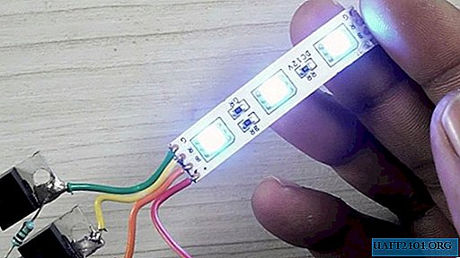
The unit is connected to an SMD5050 type LED tri-color strip or similar with 12-volt power supply. The strip contains modules, each of which contains 3 tri-color diodes. The corresponding color and power terminals, connecting in parallel, are displayed at the connection points on the canvas. The control signals of each glow are fed to the LEDs through a personal current-limiting resistor. Parallel connected modules are placed on a tape up to 5 meters long.
For a reliable connection of radio components, any soldering iron is suitable. Pliers, nippers or a knife will help to give the conclusions a convenient form for work, bend them and cut to the desired length. The unit operates from a constant current source of 12 volts.
Controller circuit assembly
There are few details, so it is convenient to make the installation by a hinged method, when the elements are soldered directly to each other without intermediate contacts, supports or assembly boards.

The transistor crystal is placed inside the plastic case. Centrally located, the Stoke is also connected to a large metal heat sink. Usually it is used for mounting on the wall of the electronic unit. The metal of the radiator is easy to tin, so it is convenient to use it as a contact pad for soldering resistance.
Its second end is connected to the "Shutter" terminal of the next element.
The third transistor is connected in a similar way, but its "Stoke" will be connected through a resistor to the "Gate" electrode of the first stage, forming a ring.

A capacitor is connected between the “Gate” and “Source” electrodes of each transistor. It is first necessary to correctly determine the polarity of the component by the marking on the case. Usually a negative electrode is marked, which is soldered to the "Source".

A piece of wire connects the Source of all transistors, creating a bus for connecting the minus terminal of the power supply. Rigid transistor electrodes are easy to push apart and stabilize to avoid accidental short circuits.


On the LED strip, the switching points "R", "G" and "B" are indicated. With pieces of insulated wire, each of them is connected to the "Stoke" of one of the transistors.

The "plus" of the current source is connected to the "+" terminal of the tape, the "minus" is soldered to the "Source" bus of the transistors.
Assembled from serviceable parts with full compliance with the installation of the circuit diagram, the controller starts working after being switched on without the need for preliminary configuration or selection of element parameters. The switching frequency will decrease with increasing capacity rating and vice versa.


Tip
Soldering will be easier and faster if the terminals of the radio components are pre-tinned. When working with a soldering iron, you need to take care of the normal ventilation of the room, be careful not to get a thermal burn or electric shock.
Watch the detailed video
Share
Pin
Tweet
Send
Share
Send