Share
Pin
Tweet
Send
Share
Send


Have you ever wanted to check your radioactivity? Or maybe you wanted to prepare for a nuclear Apocalypse? Then this master class on manufacturing a Geiger counter is just for you. I will show you how to make a very simple and cheap Geiger counter from old and unnecessary parts that were in use. Watch the video on the assembly and operation of the counter at the end of my article. Let's start!
How does a geiger counter work?


To start, I will explain the basics of how everything works. The Geiger counter uses a special tube filled with an inert gas at very low pressure to detect radiation. Inside this tube there is a cylindrical piece of metal that acts as a cathode. Inside this cylinder there is a small metal piece of wire that acts as an anode. When a high voltage is present at the anode of the tube, nothing happens, but when ray particles enter the tube, it causes ionization of an inert time, and it begins to conduct an electric current. This current can be measured by special instruments, but in this circuit there will only be detection of a signal about the presence of radiation.
Geyer counter circuit

The Geiger counter consists of two parts: a high-voltage power source - a converter and a detector. In the above diagram, the high voltage circuit consists of a timer 555, on which the generator is built. A timer 555 generates rectangular pulses, which through the resistor open and close the transistor periodically. This transistor drives a small step-up transformer. From the output transformer, the voltage is supplied to the voltage doubler, where it rises to about 500 volts. Then, the voltage is stabilized with the help of zener diodes up to 400 volts, which are needed to power the Geiger counter tube.
The detector consists of a piezoelectric element connected directly to the tube anode without any amplifiers.
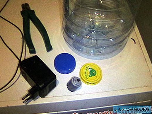
Tools & Parts


To complete this project, you will need various tools and materials.
Instruments:
- Nippers.
- Stripper for stripping wires.
- Soldering iron.
- Hot glue gun.
Details: most of them can be found from older electronic devices.
- Transformer 8: 800 - it was a transformer of a broken alarm clock power supply.
- Geiger tube - purchased - HERE.
- Timer 555.
- 47K resistors (x2).
- Capacitor 22nF.
- Capacitor 2.2 nF.
- 1K resistor.
- Any N-channel MOSFET.
- Bread board.
- 1n4007 diode (x2).
- Capacitor 100 nF at 500 volts.
- Zener Diodes - 100 Volts (x4)
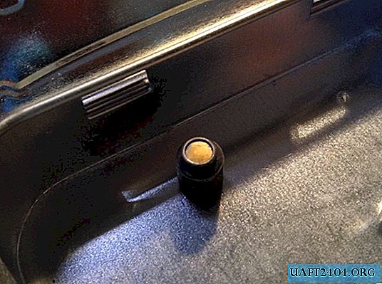
- Piezoelectric element (from an old microwave oven).
- Wires.
- Solder.
Generator assembly with a MOSFET transistor


Once you have assembled your tools and materials, it's time to go on to solder the components. The first thing you need to solder is a generator and a transistor. To do this, install each component on the breadboard in the most efficient way. For example, solder the mosfet next to where with the transformer. This will help you use less wires when soldering. As all the parts are soldered together, cut off the excess wire.
Solder the transformer and voltage doubler with stabilization


After assembling the generator, you need to solder the transformer winding with less resistance between the MOSFET plus power. Then solder the transformer output from the high voltage winding to the doubler. Then, solder all the capacitors and zener diodes. After soldering, the high-voltage power supply must be checked with a voltmeter to see that it is assembled correctly and provides the desired voltage. If you have a different Geiger tube, not like mine, look at its specifications in order to find out its supply voltage, which may differ. Then add the appropriate zener diodes.
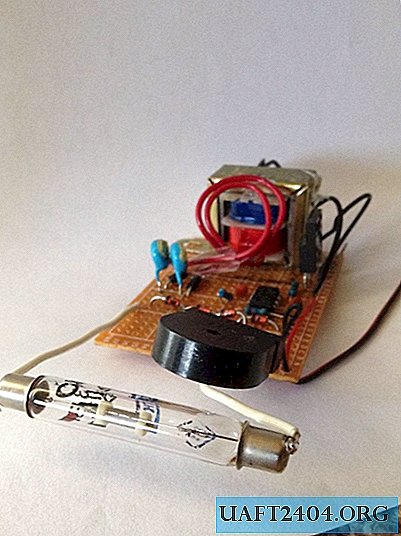
Adding a geiger tube and detector


The final part and it remains for me to add the tube itself to the circuit - the counter and detector. We begin to solder the wires to each end of the tube. Then, solder the anode to the output of the regulated power source and the cathode to the piezoelectric element. Finally, solder the piezoelectric element to the common wire. Thanks to the use of a detector consisting of only two components, this is considered the simplest Geiger counter. Most more sophisticated counters contain transistors in the detector. No current limiting resistors are needed in this detector because of very low currents.
Test


Finally, it is time to check the Geiger counter! To do this, first connect the meter to a power source. Then, take a radioactive source to check. Using pliers, hold the radiation source near the Geiger tube. You should hear a few noticeable clicks that are heard in the piezoelectric element. This means that the counter is working properly. To hear and see this, watch the video. Thanks for reading!
Watch the video of the Geiger counter
Disclaimer: This project operates with high voltage, follow safety instructions and work with caution.
Share
Pin
Tweet
Send
Share
Send