Share
Pin
Tweet
Send
Share
Send
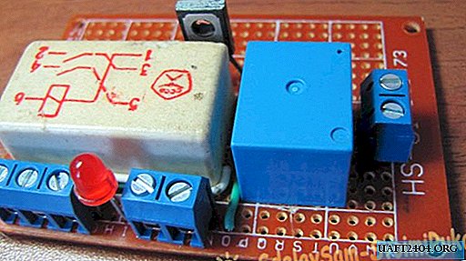
Water level control in automatic mode using the simplest electronic water level control circuit.
The whole water level control scheme consists of several simple parts and if it is assembled without any errors from good parts, it does not need to be configured and will immediately work as planned. I have been working on a similar scheme for almost three years now, and I am very pleased with it.
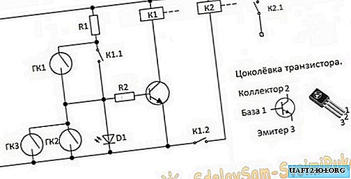
Automatic water level control circuit
Parts List
- The transistor can be used with any of these: KT815A or B. TIP29A. TIP61A. BD139. BD167. BD815.
- GK1 - reed switch of the lower level.
- GK2 - top level reed switch.
- GK3 - reed switch emergency level.
- D1 - any red LED.
- R1 - 3K resistor 0.25 watts.
- R2 - 300 ohm resistor 0.125 watts.
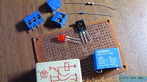
- K1 - any 12 volt relay with two pairs of normally open contacts.
- K2 - any 12 volt relay with one pair of normally open contacts.
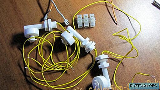
- As signal sources for replenishing water in a tank, I used float reed contacts. On the diagram are designated GK1, GK2 and GK3. Chinese production, but very decent quality. I can’t say a single bad word. In the container where they stand, I have water treated with ozone and over the years of work on them there has not been the slightest damage. Ozone is an extremely aggressive chemical element and it dissolves many plastics completely without residue.
Now consider the operation of the circuit in automatic mode.
When power is supplied to the circuit, the lower level float GK1 is activated and through its contact and resistors R1 and R2, power is supplied to the base of the transistor. The transistor opens and thereby supplies power to the relay coil K1. The relay turns on and blocks GK1 (lower level) with its contact K1.1, and with contact K1.2 it supplies power to the coil of relay K2, which is an actuator and switches on an actuator with its contact K2.1. The actuator may be a water pump or an electric valve that supplies water to the tank.
Water is replenished and when it exceeds the lower level, GK1 turns off, thereby preparing the next cycle of work. Having reached the upper level, the water will raise the float and turn on GK2 (upper level) thereby closing the chain through R1, K1.1, GK2. The power supply to the base of the transistor will be interrupted, and it will close by turning off the relay K1, which with its contacts will open K1.1 and turn off the relay K2. The relay, in turn, will turn off the actuator. The scheme is prepared for a new cycle of work. GK3 is an emergency level float and serves as insurance if the upper level float does not work suddenly. Diode D1 is an indicator of the operation of the device in the water filling mode.
And now let's start manufacturing this very useful device.
We place the details on the board.
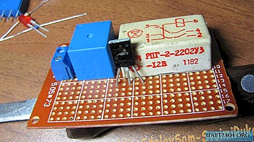
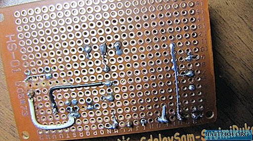
We place all the details on the breadboard so as not to make a printed circuit. When placing parts, you need to consider to solder as few jumpers as possible. It is necessary to maximize the use of the conductors of the elements themselves for installation.
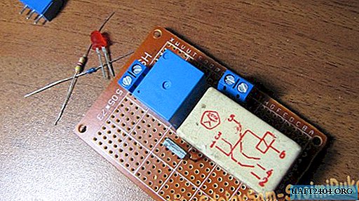
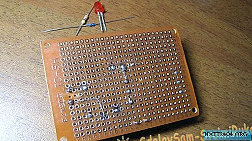
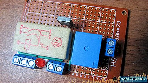
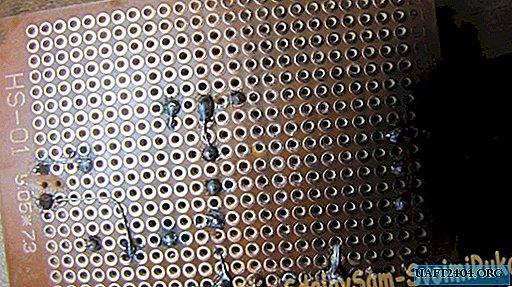
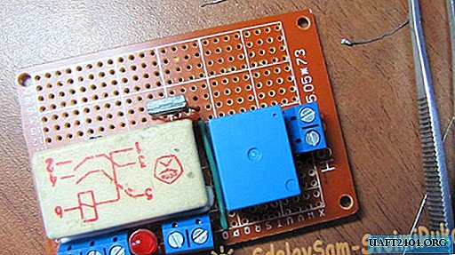
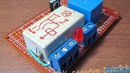
The final look.
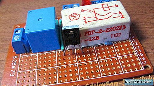
The water level control circuit is sealed.
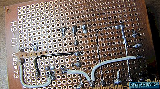
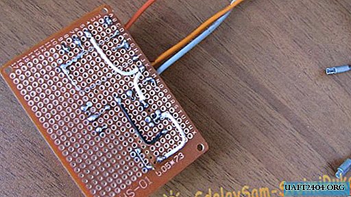
The circuit is ready for testing.
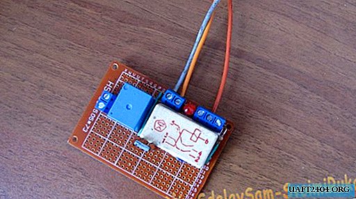
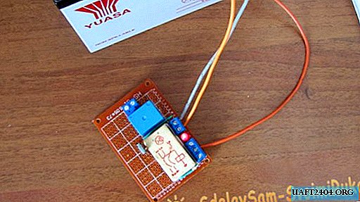
We connect to the battery and simulate the operation of the floats.
Everything is working fine. Watch a video about testing this system.
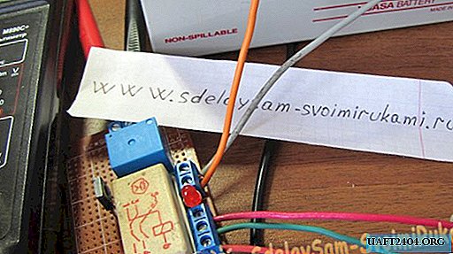
Watch the test video
Share
Pin
Tweet
Send
Share
Send

